Just saw this pop up on Engadget. Wireless repeaters that go for 1.5 miles (2.4km).
I'm thinking large stadia or live sites where you'd need to move a bunch of signals around but it would be impractical to run Cat5 across the ground, or events like the Sydney New Year's Eve fireworks where there are barges spread out across the harbour...
Press-release and first thoughts:
http://www.engadget.com/2011/10/24/amped-wireless-gives-your-wifi-1-5-mile-range-never-lose-signal/
Company Signal:
http://www.ampedwireless.com/

This is a story of technology and the people it serves.
Showing posts with label transport. Show all posts
Showing posts with label transport. Show all posts
Tuesday, October 25, 2011


Sunday, October 16, 2011
Layers of the Internet - Part 4
If you are new to this area, or are looking for the first three parts of this series, please use the following links:
Layer 1 - Link Layer
Layer 2- Internet Layer
Layer 3- Transport Layer
To recap quickly, the Link layer is the physical connection between devices (be it wireless, electrical or optical).
The Internet Layer is the layer that deals with the virtual separation of the entire Layer 1 network into smaller, virtual networks, and also allows traffic to be routed from one side of the planet to another.
The Transport Layer deals with two main things; where the data goes inside the devices that receive it, and also how the packets are passed around the networks (e.g. error correction protocols - re-sending a packet that never arrived at the destination.
Layer 4 - The Application Layer
For a second, let's think about what we are trying to achieve with a data network. We are trying to move information (be it computer data, an image, live audio... anything) from one point to another. If we look at what we've done in layers 1-3, we can see that we've done nothing but move the data from one end of the earth to the other.
.
But before any data can be delivered, we have to actually work out what data we are going to transport, why we around going to transport it and then what we are going to do with it at the other end. Data is useless unless we actually do something with it. For example, you could send a friend a photo, but if they can't view it then there was no point to transferring the data in the first place.
This is where the application layer comes in. It is the layer of the Internet that interfaces with the Users, but it is also the layer where we actually change the information that we are sending.
But Layer 4 isn't all about the Users, there's a lot of background processes involved. Let's have a quick look at a simple internet action; checking this blog:
So, from your 31 keystrokes (including the "enter" key at the end) your browser and the Server have been communicating at Layer 4. You'll notice that I barely mentioned the Layer 1-3 protocols; and that is because at Layer 4, just like all of the layers below it, the lower levels are transparent. It doesn't matter that I'm on a wireless connection and the server is on a optical fibre connection; they are connected up to Layer 3, and that's all that matters.
I'll be doing little write-ups on the various protocols as I continue to write this blog, so please stay tuned to the Glossary. Once I write an article on each protocol I will link it from the Glossary.
Layer 1 - Link Layer
Layer 2- Internet Layer
Layer 3- Transport Layer
To recap quickly, the Link layer is the physical connection between devices (be it wireless, electrical or optical).
The Internet Layer is the layer that deals with the virtual separation of the entire Layer 1 network into smaller, virtual networks, and also allows traffic to be routed from one side of the planet to another.
The Transport Layer deals with two main things; where the data goes inside the devices that receive it, and also how the packets are passed around the networks (e.g. error correction protocols - re-sending a packet that never arrived at the destination.
Layer 4 - The Application Layer
For a second, let's think about what we are trying to achieve with a data network. We are trying to move information (be it computer data, an image, live audio... anything) from one point to another. If we look at what we've done in layers 1-3, we can see that we've done nothing but move the data from one end of the earth to the other.
 |
| Layers! Layer 4 is like the river and the clouds above; they rely on the lower layers of the earth, but they don't really care about them |
.
But before any data can be delivered, we have to actually work out what data we are going to transport, why we around going to transport it and then what we are going to do with it at the other end. Data is useless unless we actually do something with it. For example, you could send a friend a photo, but if they can't view it then there was no point to transferring the data in the first place.
This is where the application layer comes in. It is the layer of the Internet that interfaces with the Users, but it is also the layer where we actually change the information that we are sending.
But Layer 4 isn't all about the Users, there's a lot of background processes involved. Let's have a quick look at a simple internet action; checking this blog:
- Step 1: You open your browser and type "http://arts-comms.blogspot.com". This is the start of the process; you enter a small amount of data; 30 characters. It's not much when you think about it.
- Step 2: Your browser tries to find the address of this page. If you were going to send a letter to a friend you couldn't just write their name on an envelope, post it, and hope for the best. The "Human-readable" Universal Resource Locator (URL) is similar to you friend's name; you can use it to describe them and look them up, but it isn't exactly an address. So, before your browser starts downloading this page, it looks out for a Domain Name Server (DNS) that will translate the URL into a TCP/IP Address.This address combines the Layer 2 and 3 addresses for the webpage. In this case the IP part of the address is 74.125.71.132, and the port is 80. This could be written 74.125.71.132:80.
- Step 3: Your browser now requests a session with the blogspot.com webserver. Now that your browser knows where to look, it will send a request to 74.125.71.132:80 to ask if it can start talking to the Server. The server will normally check that there are no bans on your device, or any other reasons that it wouldn't want to talk to you.
- Step 4: The Server opens a port and allows a session to begin. Should everything in Step 3 check out, the server will allocate a port number (this can be random, or fixed; it depends on the server) and then sends the information to your browser, letting it know that it's all good to go.
- Step 5: Your Browser requests the Webpage. Now that the Server and your browser are talking, the browser finally asks for this page, sending along with the request any additional information that might be required (e.g. your login details, or which exact page you're requesting).
- Step 6: The Server retrieves the webpage from its hard drive, and then transmits it as a series of packets. If you were to send a entire webpage as a single packet, it would be huge, and that would slow it down through the Internet. So the Server splits up the webpage into a number of small packets, adds a bit of information to let your browser know the order of the packets, and then transmits them through the network.
- Step 7: Your browser assembles the webpage, checking for errors as it goes. There is always a chance that some packets will get lost in transit. However, since the server has added information for your browser, it will know if anything is missing. If something doesn't make it then your browser will re-request the missing pieces.
- Step 8: Close the Session. Once everything has been checked, and you're happily reading away, the browser sends a message to the Server to finish off the session that was opened in Step 4. Once this is closed the connection disappears from the internet.
So, from your 31 keystrokes (including the "enter" key at the end) your browser and the Server have been communicating at Layer 4. You'll notice that I barely mentioned the Layer 1-3 protocols; and that is because at Layer 4, just like all of the layers below it, the lower levels are transparent. It doesn't matter that I'm on a wireless connection and the server is on a optical fibre connection; they are connected up to Layer 3, and that's all that matters.
I'll be doing little write-ups on the various protocols as I continue to write this blog, so please stay tuned to the Glossary. Once I write an article on each protocol I will link it from the Glossary.
Thursday, September 15, 2011
The layers of the Internet - Part 2
The Internet Layer
In the last post I explained the basics of Layer 1 of the Internet Protocol; the Link Layer.
The Link Layer is where all devices are physically connected, either by wireless (e.g. Wireless LAN or 3G) or by a wired (e.g. Ethernet "Blue String" or ADSL) connection.
Whilst this is a great concept, if every device were to receive all of the data transmitted on the Internet, then we would be slowing down the process beyond belief.
Enter Layer 2 - The Internet Layer

In the last post I explained the basics of Layer 1 of the Internet Protocol; the Link Layer.
The Link Layer is where all devices are physically connected, either by wireless (e.g. Wireless LAN or 3G) or by a wired (e.g. Ethernet "Blue String" or ADSL) connection.
Whilst this is a great concept, if every device were to receive all of the data transmitted on the Internet, then we would be slowing down the process beyond belief.
Enter Layer 2 - The Internet Layer
 |
| This is Layer 2 |
On a network drawing, a network was always drawn using standardised symbols. Since everything that was on the "Internet" was connected at Layer 1, it no longer mattered how things were connected. You only had to show that there was some kind of connection.
And so the network symbol for the "Internet" became a cloud. It was some ethereal entity, floating out of the reach of Network Administrators across the globe.
Unfortunately marketing departments caught hold of this analogy, and thus Cloud Computing was born. You can see the "Cloud", and it brings you good things (like shade, and rain for your crops) but you have little to no power over it. It's there whether you like it or not.
So how does it work?
Packet-Switching Networks
In this previous blog post I explained the anatomy of a standard Internet Protocol (IP) Packet. Packets are the currency for IP networks, and indeed the entire Internet. Without repeating myself too much, they contain two main parts; a "Payload" (the data that you want to move around the network) and a "Header" (which contains the addresses relevant to the Data).
In order to understand how the Internet works, we are going to have to introduce our first specific piece of network hardware: the Switch.

The image above is that of a "Switch," and it is a common thing to be found in data centres across the world. However you are reading this blog, somewhere along the line you are connected to a Switch. It might be a little 4-port switch that came with your ADSL plan, or you might be connected to a commercial-grade switch (like the one above) at work.
Switches are the building blocks of the Internet, and they elevate matters from Layer 1 (Link Layer) to Layer 2 (Internet Layer).
Every blue or pink cable in the above image connects to a device; a telephone, a computer, a printer etc. This is the Layer 1 connection. You can tell they are working by the blinking green lights. The Orange cables connect those switches to other switches, which the connect to other switches... until they reach whatever destination they need to get to. These connections are called "Uplink Ports", as they are headed up towards the "Cloud".
When a packet is sent to a switch, it "opens" it up and reads the "Header" (not the "Payload"). In the "Header" is all of the addressing information that the Switch needs to send the packet to where it needs to go. If the destination address is connected directly to the switch, then the packet will be sent directly to that device. If not, then the switch will send the packet to the "Uplink" port, at which point the next Switch will repeat the same process until the packet arrives at its destination.
By doing this, Switches make sure that you only receive the packets that you need to read your emails, browse your websites, control your motors, or route audio. Switches don't care what your packet has in it, so long as the address in the Header is valid.
The address used by the Internet Layer is the Internet Protocol (IP) Address. I will go into (much) more details about IP Addresses in a later post as the topic is as broad as the Internet itself. Suffice to say, a common IP address is an 8-byte address, usually rendered in four groups of numbers from 0 to 255, e.g. 192.168.0.254.
Once two devices are connected at Layer 2 they are considered "Networked" and can now communicate as if they were in the same room. Layers 3 and 4 deal with how they communicate, and we will cover these in the next blog post.
Switches are the building blocks of the Internet, and they elevate matters from Layer 1 (Link Layer) to Layer 2 (Internet Layer).
Every blue or pink cable in the above image connects to a device; a telephone, a computer, a printer etc. This is the Layer 1 connection. You can tell they are working by the blinking green lights. The Orange cables connect those switches to other switches, which the connect to other switches... until they reach whatever destination they need to get to. These connections are called "Uplink Ports", as they are headed up towards the "Cloud".
When a packet is sent to a switch, it "opens" it up and reads the "Header" (not the "Payload"). In the "Header" is all of the addressing information that the Switch needs to send the packet to where it needs to go. If the destination address is connected directly to the switch, then the packet will be sent directly to that device. If not, then the switch will send the packet to the "Uplink" port, at which point the next Switch will repeat the same process until the packet arrives at its destination.
By doing this, Switches make sure that you only receive the packets that you need to read your emails, browse your websites, control your motors, or route audio. Switches don't care what your packet has in it, so long as the address in the Header is valid.
The address used by the Internet Layer is the Internet Protocol (IP) Address. I will go into (much) more details about IP Addresses in a later post as the topic is as broad as the Internet itself. Suffice to say, a common IP address is an 8-byte address, usually rendered in four groups of numbers from 0 to 255, e.g. 192.168.0.254.
Once two devices are connected at Layer 2 they are considered "Networked" and can now communicate as if they were in the same room. Layers 3 and 4 deal with how they communicate, and we will cover these in the next blog post.
Monday, August 15, 2011
Time Division Multiplexing - TDM (the root of all good)
Rise of the Packets
In this post, I looked into the concept of Packets. I have a great fondness for packets, as it is packets that move the majority of the data in the world.
They are really good at moving data around in an ad-hoc fashion. Any piece of data can be broken down, transmitted and reassembled without any distortion.
Fall of the Packets
But that process is slow. It can take milliseconds to disassemble the data into manageable chunks, then add in all of the extra address, protocol information... and the data hasn't even left your device yet.
Obviously, when it comes to emails, images, or text a delay of even a couple of hundred milliseconds isn't going to be noticed by a mere human. So once again, the packet wins.
Time-critical Applications
However, let's take audio. I will go into how digital audio works at a later stage, but for now you should know that digital audio (e.g. CDs, common live audio mixers, MP3s etc) is made up of 24-bits of data, give or take. (a "bit" is a 0 or a 1). This is repeated around about 48 thousand times a second; or once every 0.02 milliseconds.
So, if the a "packet" of audio data arrived milliseconds out of sequence, we would end up with noise. And not the good type; I'm thinking Lou Reid's Metal Machine Music.
A Saviour in time
To get around this we need a faster method of transport. Enter Time-Division Multiplexing!
Modern computing equipment is more than capable of processing things at speeds fast enough for "real-time" applications like audio. A 2.66 GHz processor (like one of the 8 I am using now) can process a "sample" (that 24-bit thing I was talking about before) in about 0.3 nanoseconds.
For those of you that don't like maths, that's about 65,000 audio "samples" per "Sample"; meaning that any one of my 8 processors could play music for me and still only be working to 1/65,000th of its capacity.

Okay, so those numbers may have caused you to glaze over. Hence the "bird on the wire" to liven things up.
The thing to take away from the maths above is that even a fairly stock-standard computer takes one look at time-critical audio and laughs it off.
So, how can this help us with faster data transport?
Enter Time-division Multiplexing
The simplest way is to give each "device," or data-source, an "address" that corresponds to a certain time.
This "address" will then offset the data from each device by a certain time; device 0 will have a 0s offset; device 1 will have an offset of 0.02 microseconds, device 2 will have an offset of 0.04 microseconds... until we get to device 65,000 something.
Let's have a look at the diagram below:
 Here we only have two devices; Red and Green. Green has address "0" and Red has address "1".
First up, the Green wants to transmit some data, so it goes into the first "timeslot" (a timeslot is the base unit of a TDM network; kind of like a packet). Since there is no "Red" data in the first timeslot, the next slot is blank.
However in the second "Timeslot" both Green and Red want to transmit something. Green goes first and transmits its data, and then Red transmits, so we see a Green block and then a Red block.
And so on; each device waits for its turn, then transmits the data.
To read the data you need to know which data you are looking for, wait until that "timeslot" appears, and then read the data.

Forgiving the Chinese characters, this image shows the same concept, but for more devices. On the left we see all of the data that we want to transmit. In the middle we can see that each device waits until it is their turn, then transmits like crazy.
On the right hand side we can pick out any particular timeslot and read the data.
Why should we care?
One thing that you may have noticed in the above is that all of the devices have the ability to read all of the data on the network.
Time-Division Multiplexing (TDM) Networks are relatively simple; each device is directly connected to the next, and will usually transmit the entirety of the data to all connected devices.
One application that really likes this is large matrices. For example, take a communications. You could have 100 people trying to talk to each other. Any one of those 100 people may want to talk to any (or all) of the other 99 users at once.
A TDM Network makes mincemeat of this; each user is allocated a timeslot on the network. When they talk, their audio fills up their timeslot. When they aren't talking, nothing is transmitted (remember our Red and Green above).
At the other end, the user receiving the call pulls out the audio from all of the timeslots that they want to listen to.
Of course, this requires a bit of computer processing, but most common communications networks are more than capable of handling thousands of users on one TDM network.
In fact, most matrix routers/switchers employ a TDM network of one kind of another. The concept of a TDM can be applied inside a single "box". For example, a video matrix. Each input takes up one timeslot; each output reads from one timeslot. In this way, any input can go to any output without causing interruption to the video. When a TDM is contained in a single box, it is usually referred to as a backplane.
Downfalls?
The biggest drawback of a TDM TDM network is limited not by the address space, but by the processing speed of the devices and the size of the data being transmitted. Transmitting audio through a computer's processor gives many thousands of audio channels, however transmitting high-definition video over standard networking architecture yields only tens of channels.
TDM networks need to be connected to all other devices in the network. There are some funky devices out there that will bridge two TDM networks, but these are usually limited.
TDM networks are also super sensitive to clocking. Once again, I'll go into clocking in a different article, but for the time being think of it this way.
Think of all of the timeslots as trains. However on TDM station there aren't any "The next train goes to Sydney" announcements, there is only a timetable.
If you only have your wristwatch to go on, you may catch the wrong train; how do you know that your 1:13 is the same as the railway's 1:13?
However, if there is a clock on the station, and one on the train, then you can confirm that your train is the right one before you board.
The same thing happens with TDM; unless you synchronise all of the devices you have no way of knowing which "train" (timeslot) is the right one.
Conclusion
I hope you have enjoyed this. Please comment if you don't "get it" and I will edit this post in order to make it easier to understand.
TDM networks are prevalent in audio, video and communications networks, and that's why I wanted to get this up earlier rather than later. Apologies for the maths earlier; I hope the bird picture helped you through that.
In this post, I looked into the concept of Packets. I have a great fondness for packets, as it is packets that move the majority of the data in the world.
They are really good at moving data around in an ad-hoc fashion. Any piece of data can be broken down, transmitted and reassembled without any distortion.
Fall of the Packets
But that process is slow. It can take milliseconds to disassemble the data into manageable chunks, then add in all of the extra address, protocol information... and the data hasn't even left your device yet.
Obviously, when it comes to emails, images, or text a delay of even a couple of hundred milliseconds isn't going to be noticed by a mere human. So once again, the packet wins.
Time-critical Applications
However, let's take audio. I will go into how digital audio works at a later stage, but for now you should know that digital audio (e.g. CDs, common live audio mixers, MP3s etc) is made up of 24-bits of data, give or take. (a "bit" is a 0 or a 1). This is repeated around about 48 thousand times a second; or once every 0.02 milliseconds.
So, if the a "packet" of audio data arrived milliseconds out of sequence, we would end up with noise. And not the good type; I'm thinking Lou Reid's Metal Machine Music.
A Saviour in time
To get around this we need a faster method of transport. Enter Time-Division Multiplexing!
Modern computing equipment is more than capable of processing things at speeds fast enough for "real-time" applications like audio. A 2.66 GHz processor (like one of the 8 I am using now) can process a "sample" (that 24-bit thing I was talking about before) in about 0.3 nanoseconds.
For those of you that don't like maths, that's about 65,000 audio "samples" per "Sample"; meaning that any one of my 8 processors could play music for me and still only be working to 1/65,000th of its capacity.

Okay, so those numbers may have caused you to glaze over. Hence the "bird on the wire" to liven things up.
The thing to take away from the maths above is that even a fairly stock-standard computer takes one look at time-critical audio and laughs it off.
So, how can this help us with faster data transport?
Enter Time-division Multiplexing
The simplest way is to give each "device," or data-source, an "address" that corresponds to a certain time.
This "address" will then offset the data from each device by a certain time; device 0 will have a 0s offset; device 1 will have an offset of 0.02 microseconds, device 2 will have an offset of 0.04 microseconds... until we get to device 65,000 something.
Let's have a look at the diagram below:

First up, the Green wants to transmit some data, so it goes into the first "timeslot" (a timeslot is the base unit of a TDM network; kind of like a packet). Since there is no "Red" data in the first timeslot, the next slot is blank.
However in the second "Timeslot" both Green and Red want to transmit something. Green goes first and transmits its data, and then Red transmits, so we see a Green block and then a Red block.
And so on; each device waits for its turn, then transmits the data.
To read the data you need to know which data you are looking for, wait until that "timeslot" appears, and then read the data.
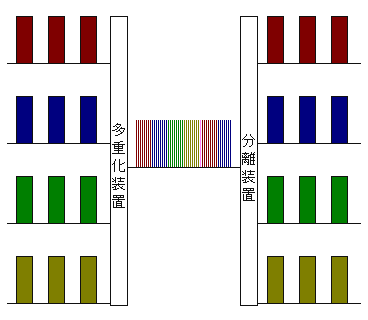
Forgiving the Chinese characters, this image shows the same concept, but for more devices. On the left we see all of the data that we want to transmit. In the middle we can see that each device waits until it is their turn, then transmits like crazy.
On the right hand side we can pick out any particular timeslot and read the data.
Why should we care?
One thing that you may have noticed in the above is that all of the devices have the ability to read all of the data on the network.
Time-Division Multiplexing (TDM) Networks are relatively simple; each device is directly connected to the next, and will usually transmit the entirety of the data to all connected devices.
One application that really likes this is large matrices. For example, take a communications. You could have 100 people trying to talk to each other. Any one of those 100 people may want to talk to any (or all) of the other 99 users at once.
A TDM Network makes mincemeat of this; each user is allocated a timeslot on the network. When they talk, their audio fills up their timeslot. When they aren't talking, nothing is transmitted (remember our Red and Green above).
At the other end, the user receiving the call pulls out the audio from all of the timeslots that they want to listen to.
Of course, this requires a bit of computer processing, but most common communications networks are more than capable of handling thousands of users on one TDM network.
In fact, most matrix routers/switchers employ a TDM network of one kind of another. The concept of a TDM can be applied inside a single "box". For example, a video matrix. Each input takes up one timeslot; each output reads from one timeslot. In this way, any input can go to any output without causing interruption to the video. When a TDM is contained in a single box, it is usually referred to as a backplane.
Downfalls?
The biggest drawback of a TDM TDM network is limited not by the address space, but by the processing speed of the devices and the size of the data being transmitted. Transmitting audio through a computer's processor gives many thousands of audio channels, however transmitting high-definition video over standard networking architecture yields only tens of channels.
TDM networks need to be connected to all other devices in the network. There are some funky devices out there that will bridge two TDM networks, but these are usually limited.
TDM networks are also super sensitive to clocking. Once again, I'll go into clocking in a different article, but for the time being think of it this way.
Think of all of the timeslots as trains. However on TDM station there aren't any "The next train goes to Sydney" announcements, there is only a timetable.
If you only have your wristwatch to go on, you may catch the wrong train; how do you know that your 1:13 is the same as the railway's 1:13?
However, if there is a clock on the station, and one on the train, then you can confirm that your train is the right one before you board.
The same thing happens with TDM; unless you synchronise all of the devices you have no way of knowing which "train" (timeslot) is the right one.
Conclusion
I hope you have enjoyed this. Please comment if you don't "get it" and I will edit this post in order to make it easier to understand.
TDM networks are prevalent in audio, video and communications networks, and that's why I wanted to get this up earlier rather than later. Apologies for the maths earlier; I hope the bird picture helped you through that.
Subscribe to:
Posts (Atom)