http://www.engadget.com/2011/09/16/fcc-to-test-white-space-database-at-its-own-pace/
I know that I have been hoping to drip-feed information here, but occasionally I will need to jump the gun.
For those of you that don't know about the "White Space," it is referring to the spaces in the RF Spectrum that will be left between Television Channels, leaving clear bandwidth for devices to communicate on.
This spectrum remains unlicensed, and thus manufacturers can use this space for data transfer. Wireless Microphones operate in the same space; they are designed to work in the TV channel space, but in the "gaps" between channels. Of course, the introduction of more "White Space" devices sends shivers up most Radio Mic Technician's spine, because it potentially means that a device will suddenly appear in the middle of your spectrum... when you least expect it!
The reason White Space Devices didn't work so well in the past is due to the difference between Digital and Analogue TV transmission. Analogue is much less predictable, however Digital Channels stick out like a sore thumb to even the most basic devices. So, when you turn off the Analogue stations, you make it a lot easier to make White Space Devices.
It shouldn't be confused with the Digital Dividend, which is the space at the high end (~800MHz) of the spectrum that will be "empty" (i.e. no TV channels) once the Analogue TV stations are turned off. This spectrum will be sold off, and in the US it made a hell of a lot of money.
I will go into all of these topics in much greater detail, but for those of you that are hanging on any bit of Spectrum Information, please enjoy the link.

This is a story of technology and the people it serves.
Sunday, September 18, 2011


Thursday, September 15, 2011
The layers of the Internet - Part 2
The Internet Layer
In the last post I explained the basics of Layer 1 of the Internet Protocol; the Link Layer.
The Link Layer is where all devices are physically connected, either by wireless (e.g. Wireless LAN or 3G) or by a wired (e.g. Ethernet "Blue String" or ADSL) connection.
Whilst this is a great concept, if every device were to receive all of the data transmitted on the Internet, then we would be slowing down the process beyond belief.
Enter Layer 2 - The Internet Layer

In the last post I explained the basics of Layer 1 of the Internet Protocol; the Link Layer.
The Link Layer is where all devices are physically connected, either by wireless (e.g. Wireless LAN or 3G) or by a wired (e.g. Ethernet "Blue String" or ADSL) connection.
Whilst this is a great concept, if every device were to receive all of the data transmitted on the Internet, then we would be slowing down the process beyond belief.
Enter Layer 2 - The Internet Layer
 |
| This is Layer 2 |
On a network drawing, a network was always drawn using standardised symbols. Since everything that was on the "Internet" was connected at Layer 1, it no longer mattered how things were connected. You only had to show that there was some kind of connection.
And so the network symbol for the "Internet" became a cloud. It was some ethereal entity, floating out of the reach of Network Administrators across the globe.
Unfortunately marketing departments caught hold of this analogy, and thus Cloud Computing was born. You can see the "Cloud", and it brings you good things (like shade, and rain for your crops) but you have little to no power over it. It's there whether you like it or not.
So how does it work?
Packet-Switching Networks
In this previous blog post I explained the anatomy of a standard Internet Protocol (IP) Packet. Packets are the currency for IP networks, and indeed the entire Internet. Without repeating myself too much, they contain two main parts; a "Payload" (the data that you want to move around the network) and a "Header" (which contains the addresses relevant to the Data).
In order to understand how the Internet works, we are going to have to introduce our first specific piece of network hardware: the Switch.

The image above is that of a "Switch," and it is a common thing to be found in data centres across the world. However you are reading this blog, somewhere along the line you are connected to a Switch. It might be a little 4-port switch that came with your ADSL plan, or you might be connected to a commercial-grade switch (like the one above) at work.
Switches are the building blocks of the Internet, and they elevate matters from Layer 1 (Link Layer) to Layer 2 (Internet Layer).
Every blue or pink cable in the above image connects to a device; a telephone, a computer, a printer etc. This is the Layer 1 connection. You can tell they are working by the blinking green lights. The Orange cables connect those switches to other switches, which the connect to other switches... until they reach whatever destination they need to get to. These connections are called "Uplink Ports", as they are headed up towards the "Cloud".
When a packet is sent to a switch, it "opens" it up and reads the "Header" (not the "Payload"). In the "Header" is all of the addressing information that the Switch needs to send the packet to where it needs to go. If the destination address is connected directly to the switch, then the packet will be sent directly to that device. If not, then the switch will send the packet to the "Uplink" port, at which point the next Switch will repeat the same process until the packet arrives at its destination.
By doing this, Switches make sure that you only receive the packets that you need to read your emails, browse your websites, control your motors, or route audio. Switches don't care what your packet has in it, so long as the address in the Header is valid.
The address used by the Internet Layer is the Internet Protocol (IP) Address. I will go into (much) more details about IP Addresses in a later post as the topic is as broad as the Internet itself. Suffice to say, a common IP address is an 8-byte address, usually rendered in four groups of numbers from 0 to 255, e.g. 192.168.0.254.
Once two devices are connected at Layer 2 they are considered "Networked" and can now communicate as if they were in the same room. Layers 3 and 4 deal with how they communicate, and we will cover these in the next blog post.
Switches are the building blocks of the Internet, and they elevate matters from Layer 1 (Link Layer) to Layer 2 (Internet Layer).
Every blue or pink cable in the above image connects to a device; a telephone, a computer, a printer etc. This is the Layer 1 connection. You can tell they are working by the blinking green lights. The Orange cables connect those switches to other switches, which the connect to other switches... until they reach whatever destination they need to get to. These connections are called "Uplink Ports", as they are headed up towards the "Cloud".
When a packet is sent to a switch, it "opens" it up and reads the "Header" (not the "Payload"). In the "Header" is all of the addressing information that the Switch needs to send the packet to where it needs to go. If the destination address is connected directly to the switch, then the packet will be sent directly to that device. If not, then the switch will send the packet to the "Uplink" port, at which point the next Switch will repeat the same process until the packet arrives at its destination.
By doing this, Switches make sure that you only receive the packets that you need to read your emails, browse your websites, control your motors, or route audio. Switches don't care what your packet has in it, so long as the address in the Header is valid.
The address used by the Internet Layer is the Internet Protocol (IP) Address. I will go into (much) more details about IP Addresses in a later post as the topic is as broad as the Internet itself. Suffice to say, a common IP address is an 8-byte address, usually rendered in four groups of numbers from 0 to 255, e.g. 192.168.0.254.
Once two devices are connected at Layer 2 they are considered "Networked" and can now communicate as if they were in the same room. Layers 3 and 4 deal with how they communicate, and we will cover these in the next blog post.
Monday, September 12, 2011
The Layers of the Internet - Part 1
The Internet is a complex place. There are many articles about the history of the internet, and it's a little beyond the scope of what this blog is about, so I won't go into it too much.
Suffice to say, the only way the internet works is through rigorous adherence to global standards. These standards were developed over the 15-year genesis of the Internet from research labs to commercial use.
One of the best ways to describe how these standards, and indeed the entire internet, works is known as the "layer" method.
Layers are a great way to explain many things, and the layers that we will be looking at today not only apply to networking, but to almost every form of computing or digital signal processing.
There are four layers in the "standard" Internet topology:
Those short little descriptions probably mean very little to most of you, so let me break it down a little bit more.
The Link Layer
When I think of the best way to describe the Link Layer, this image comes to mind:

What you're looking at there is a fairly typical "Distribution" switch, and a lot of optical fibre.
The Link Layer is the only physical connection layer in the Internet Protocol. It defines all the different ways that you can connect devices together if you want them to be on the internet.
If you put your mind to it, you could easily rattle off a lot of the different standards that are in the Link Layer, for example:
Suffice to say, the only way the internet works is through rigorous adherence to global standards. These standards were developed over the 15-year genesis of the Internet from research labs to commercial use.
One of the best ways to describe how these standards, and indeed the entire internet, works is known as the "layer" method.
Layers are a great way to explain many things, and the layers that we will be looking at today not only apply to networking, but to almost every form of computing or digital signal processing.
There are four layers in the "standard" Internet topology:
- Layer 1: Link Layer. This is the physical link between devices
- Layer 2: Internet Layer. This is the "virtual" layer where the data moves around networks
- Layer 3: Transport Layer. This layer defines how data moves around devices
- Layer 4: Application Layer. This is the layer that shows how data is shared between programs.
Those short little descriptions probably mean very little to most of you, so let me break it down a little bit more.
The Link Layer
When I think of the best way to describe the Link Layer, this image comes to mind:

What you're looking at there is a fairly typical "Distribution" switch, and a lot of optical fibre.
The Link Layer is the only physical connection layer in the Internet Protocol. It defines all the different ways that you can connect devices together if you want them to be on the internet.
If you put your mind to it, you could easily rattle off a lot of the different standards that are in the Link Layer, for example:
- Wireless Networking
- Ethernet networking (a.k.a. "Blue String" - those blue cables that we are all familiar with)
- Fibre Networking
- ADSL (Asymmetric Digital Subscriber Line - The way most of us get our Home internet)
- 3G/HSDPA - The wireless Broadband that most of us use on our phones.
- DOCSIS, a.k.a "Cable Internet" - networking over Coaxial cable, similar to Cable TV (Thanks djzort)
The list goes on. The greatest thing about the "Layer" system of the Internet is that it doesn't matter how you connect devices together at the Link Layer, so long as they follow the Link Layer Standards. As soon as you have that "blinking light" that shows you are connected then you can start passing information around the Internet Layer.
The Link Layer extends across the entire Internet. Just ponder on that for a second; every device that is connected to the Internet is in some way, shape or form, connected. The Link Layer is the only layer at which every device is connected; once you start moving into the "Virtual" layers (layers 2-4) you start segregating devices into separate virtual networks (or "subnets"). But for now, let's just muse on the topic of every device acting together in synchronism.
The last thing that I will mention about the Link Layer is the address that applies to it. Obviously there is no point in connecting every device on the planet unless you knew which one you wanted to talk to. Therefore every device that connects to the internet has a unique address. This address, known as the Media Access Control (MAC) address, is a unique number assigned by the manufacturer.
The MAC Address is a 48-bit number (that is, 48 "1's" or "0's"), which makes for about 300 Trillion different addresses. Every single device that is capable of connecting to a network has a MAC address. This laptop, for example, has two addresses; one for the Wireless connection and one for the hard-wired connection. Even so, the IEEE doesn't expect that we'll run out of MAC addresses this century.
We'll look at the Internet Layer next time (probably in a couple of days). I thought it best to break things up for now.
The Link Layer extends across the entire Internet. Just ponder on that for a second; every device that is connected to the Internet is in some way, shape or form, connected. The Link Layer is the only layer at which every device is connected; once you start moving into the "Virtual" layers (layers 2-4) you start segregating devices into separate virtual networks (or "subnets"). But for now, let's just muse on the topic of every device acting together in synchronism.
The last thing that I will mention about the Link Layer is the address that applies to it. Obviously there is no point in connecting every device on the planet unless you knew which one you wanted to talk to. Therefore every device that connects to the internet has a unique address. This address, known as the Media Access Control (MAC) address, is a unique number assigned by the manufacturer.
The MAC Address is a 48-bit number (that is, 48 "1's" or "0's"), which makes for about 300 Trillion different addresses. Every single device that is capable of connecting to a network has a MAC address. This laptop, for example, has two addresses; one for the Wireless connection and one for the hard-wired connection. Even so, the IEEE doesn't expect that we'll run out of MAC addresses this century.
We'll look at the Internet Layer next time (probably in a couple of days). I thought it best to break things up for now.
Monday, August 15, 2011
Time Division Multiplexing - TDM (the root of all good)
Rise of the Packets
In this post, I looked into the concept of Packets. I have a great fondness for packets, as it is packets that move the majority of the data in the world.
They are really good at moving data around in an ad-hoc fashion. Any piece of data can be broken down, transmitted and reassembled without any distortion.
Fall of the Packets
But that process is slow. It can take milliseconds to disassemble the data into manageable chunks, then add in all of the extra address, protocol information... and the data hasn't even left your device yet.
Obviously, when it comes to emails, images, or text a delay of even a couple of hundred milliseconds isn't going to be noticed by a mere human. So once again, the packet wins.
Time-critical Applications
However, let's take audio. I will go into how digital audio works at a later stage, but for now you should know that digital audio (e.g. CDs, common live audio mixers, MP3s etc) is made up of 24-bits of data, give or take. (a "bit" is a 0 or a 1). This is repeated around about 48 thousand times a second; or once every 0.02 milliseconds.
So, if the a "packet" of audio data arrived milliseconds out of sequence, we would end up with noise. And not the good type; I'm thinking Lou Reid's Metal Machine Music.
A Saviour in time
To get around this we need a faster method of transport. Enter Time-Division Multiplexing!
Modern computing equipment is more than capable of processing things at speeds fast enough for "real-time" applications like audio. A 2.66 GHz processor (like one of the 8 I am using now) can process a "sample" (that 24-bit thing I was talking about before) in about 0.3 nanoseconds.
For those of you that don't like maths, that's about 65,000 audio "samples" per "Sample"; meaning that any one of my 8 processors could play music for me and still only be working to 1/65,000th of its capacity.

Okay, so those numbers may have caused you to glaze over. Hence the "bird on the wire" to liven things up.
The thing to take away from the maths above is that even a fairly stock-standard computer takes one look at time-critical audio and laughs it off.
So, how can this help us with faster data transport?
Enter Time-division Multiplexing
The simplest way is to give each "device," or data-source, an "address" that corresponds to a certain time.
This "address" will then offset the data from each device by a certain time; device 0 will have a 0s offset; device 1 will have an offset of 0.02 microseconds, device 2 will have an offset of 0.04 microseconds... until we get to device 65,000 something.
Let's have a look at the diagram below:
 Here we only have two devices; Red and Green. Green has address "0" and Red has address "1".
First up, the Green wants to transmit some data, so it goes into the first "timeslot" (a timeslot is the base unit of a TDM network; kind of like a packet). Since there is no "Red" data in the first timeslot, the next slot is blank.
However in the second "Timeslot" both Green and Red want to transmit something. Green goes first and transmits its data, and then Red transmits, so we see a Green block and then a Red block.
And so on; each device waits for its turn, then transmits the data.
To read the data you need to know which data you are looking for, wait until that "timeslot" appears, and then read the data.

Forgiving the Chinese characters, this image shows the same concept, but for more devices. On the left we see all of the data that we want to transmit. In the middle we can see that each device waits until it is their turn, then transmits like crazy.
On the right hand side we can pick out any particular timeslot and read the data.
Why should we care?
One thing that you may have noticed in the above is that all of the devices have the ability to read all of the data on the network.
Time-Division Multiplexing (TDM) Networks are relatively simple; each device is directly connected to the next, and will usually transmit the entirety of the data to all connected devices.
One application that really likes this is large matrices. For example, take a communications. You could have 100 people trying to talk to each other. Any one of those 100 people may want to talk to any (or all) of the other 99 users at once.
A TDM Network makes mincemeat of this; each user is allocated a timeslot on the network. When they talk, their audio fills up their timeslot. When they aren't talking, nothing is transmitted (remember our Red and Green above).
At the other end, the user receiving the call pulls out the audio from all of the timeslots that they want to listen to.
Of course, this requires a bit of computer processing, but most common communications networks are more than capable of handling thousands of users on one TDM network.
In fact, most matrix routers/switchers employ a TDM network of one kind of another. The concept of a TDM can be applied inside a single "box". For example, a video matrix. Each input takes up one timeslot; each output reads from one timeslot. In this way, any input can go to any output without causing interruption to the video. When a TDM is contained in a single box, it is usually referred to as a backplane.
Downfalls?
The biggest drawback of a TDM TDM network is limited not by the address space, but by the processing speed of the devices and the size of the data being transmitted. Transmitting audio through a computer's processor gives many thousands of audio channels, however transmitting high-definition video over standard networking architecture yields only tens of channels.
TDM networks need to be connected to all other devices in the network. There are some funky devices out there that will bridge two TDM networks, but these are usually limited.
TDM networks are also super sensitive to clocking. Once again, I'll go into clocking in a different article, but for the time being think of it this way.
Think of all of the timeslots as trains. However on TDM station there aren't any "The next train goes to Sydney" announcements, there is only a timetable.
If you only have your wristwatch to go on, you may catch the wrong train; how do you know that your 1:13 is the same as the railway's 1:13?
However, if there is a clock on the station, and one on the train, then you can confirm that your train is the right one before you board.
The same thing happens with TDM; unless you synchronise all of the devices you have no way of knowing which "train" (timeslot) is the right one.
Conclusion
I hope you have enjoyed this. Please comment if you don't "get it" and I will edit this post in order to make it easier to understand.
TDM networks are prevalent in audio, video and communications networks, and that's why I wanted to get this up earlier rather than later. Apologies for the maths earlier; I hope the bird picture helped you through that.
In this post, I looked into the concept of Packets. I have a great fondness for packets, as it is packets that move the majority of the data in the world.
They are really good at moving data around in an ad-hoc fashion. Any piece of data can be broken down, transmitted and reassembled without any distortion.
Fall of the Packets
But that process is slow. It can take milliseconds to disassemble the data into manageable chunks, then add in all of the extra address, protocol information... and the data hasn't even left your device yet.
Obviously, when it comes to emails, images, or text a delay of even a couple of hundred milliseconds isn't going to be noticed by a mere human. So once again, the packet wins.
Time-critical Applications
However, let's take audio. I will go into how digital audio works at a later stage, but for now you should know that digital audio (e.g. CDs, common live audio mixers, MP3s etc) is made up of 24-bits of data, give or take. (a "bit" is a 0 or a 1). This is repeated around about 48 thousand times a second; or once every 0.02 milliseconds.
So, if the a "packet" of audio data arrived milliseconds out of sequence, we would end up with noise. And not the good type; I'm thinking Lou Reid's Metal Machine Music.
A Saviour in time
To get around this we need a faster method of transport. Enter Time-Division Multiplexing!
Modern computing equipment is more than capable of processing things at speeds fast enough for "real-time" applications like audio. A 2.66 GHz processor (like one of the 8 I am using now) can process a "sample" (that 24-bit thing I was talking about before) in about 0.3 nanoseconds.
For those of you that don't like maths, that's about 65,000 audio "samples" per "Sample"; meaning that any one of my 8 processors could play music for me and still only be working to 1/65,000th of its capacity.

Okay, so those numbers may have caused you to glaze over. Hence the "bird on the wire" to liven things up.
The thing to take away from the maths above is that even a fairly stock-standard computer takes one look at time-critical audio and laughs it off.
So, how can this help us with faster data transport?
Enter Time-division Multiplexing
The simplest way is to give each "device," or data-source, an "address" that corresponds to a certain time.
This "address" will then offset the data from each device by a certain time; device 0 will have a 0s offset; device 1 will have an offset of 0.02 microseconds, device 2 will have an offset of 0.04 microseconds... until we get to device 65,000 something.
Let's have a look at the diagram below:

First up, the Green wants to transmit some data, so it goes into the first "timeslot" (a timeslot is the base unit of a TDM network; kind of like a packet). Since there is no "Red" data in the first timeslot, the next slot is blank.
However in the second "Timeslot" both Green and Red want to transmit something. Green goes first and transmits its data, and then Red transmits, so we see a Green block and then a Red block.
And so on; each device waits for its turn, then transmits the data.
To read the data you need to know which data you are looking for, wait until that "timeslot" appears, and then read the data.
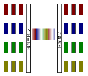
Forgiving the Chinese characters, this image shows the same concept, but for more devices. On the left we see all of the data that we want to transmit. In the middle we can see that each device waits until it is their turn, then transmits like crazy.
On the right hand side we can pick out any particular timeslot and read the data.
Why should we care?
One thing that you may have noticed in the above is that all of the devices have the ability to read all of the data on the network.
Time-Division Multiplexing (TDM) Networks are relatively simple; each device is directly connected to the next, and will usually transmit the entirety of the data to all connected devices.
One application that really likes this is large matrices. For example, take a communications. You could have 100 people trying to talk to each other. Any one of those 100 people may want to talk to any (or all) of the other 99 users at once.
A TDM Network makes mincemeat of this; each user is allocated a timeslot on the network. When they talk, their audio fills up their timeslot. When they aren't talking, nothing is transmitted (remember our Red and Green above).
At the other end, the user receiving the call pulls out the audio from all of the timeslots that they want to listen to.
Of course, this requires a bit of computer processing, but most common communications networks are more than capable of handling thousands of users on one TDM network.
In fact, most matrix routers/switchers employ a TDM network of one kind of another. The concept of a TDM can be applied inside a single "box". For example, a video matrix. Each input takes up one timeslot; each output reads from one timeslot. In this way, any input can go to any output without causing interruption to the video. When a TDM is contained in a single box, it is usually referred to as a backplane.
Downfalls?
The biggest drawback of a TDM TDM network is limited not by the address space, but by the processing speed of the devices and the size of the data being transmitted. Transmitting audio through a computer's processor gives many thousands of audio channels, however transmitting high-definition video over standard networking architecture yields only tens of channels.
TDM networks need to be connected to all other devices in the network. There are some funky devices out there that will bridge two TDM networks, but these are usually limited.
TDM networks are also super sensitive to clocking. Once again, I'll go into clocking in a different article, but for the time being think of it this way.
Think of all of the timeslots as trains. However on TDM station there aren't any "The next train goes to Sydney" announcements, there is only a timetable.
If you only have your wristwatch to go on, you may catch the wrong train; how do you know that your 1:13 is the same as the railway's 1:13?
However, if there is a clock on the station, and one on the train, then you can confirm that your train is the right one before you board.
The same thing happens with TDM; unless you synchronise all of the devices you have no way of knowing which "train" (timeslot) is the right one.
Conclusion
I hope you have enjoyed this. Please comment if you don't "get it" and I will edit this post in order to make it easier to understand.
TDM networks are prevalent in audio, video and communications networks, and that's why I wanted to get this up earlier rather than later. Apologies for the maths earlier; I hope the bird picture helped you through that.
Tuesday, August 9, 2011
Arts Communication Session at Integrate Sydney 2011
This week I received confirmation that my seminar session has been accepted for the 2011 Integrate show.
I will be presenting with Ben Moore from ARUP Theatres and Nich Young from the Sydney Opera House.
We will be discussing the applications of networks in Theatres and Performance spaces, as well as the advantages (and disadvantages) of a converged network.
So feel free to pop on down; 1430 at the RHI Mezzanine on Day 3 (Thursday, 1st of September 2011).
We even have a spot in the official show guide.
Look forward to seeing people there
I will be presenting with Ben Moore from ARUP Theatres and Nich Young from the Sydney Opera House.
We will be discussing the applications of networks in Theatres and Performance spaces, as well as the advantages (and disadvantages) of a converged network.
So feel free to pop on down; 1430 at the RHI Mezzanine on Day 3 (Thursday, 1st of September 2011).
We even have a spot in the official show guide.
Look forward to seeing people there
Sunday, July 31, 2011
What is a Packet?
Packet-switching networks, or simply Packet networks, are the most common form of network around.
But what exactly is a "packet"?
Basically, a packet is a bit of information, formatted to move around its specific network. It usually consists of two parts; a payload and formatting/addressing information. The payload can be anything that can be digitised.
For those of us coming from the Audio side of things, we're already used to the thought of packeting information. Think about a Digital audio stream. We find out the amplitude of the analogue audio signal and convert it to 1's and 0's. But before we send it around our mixer, CD player or whatever, we also put a few extra bits of information into it; how many samples per second, if it is a stereo or a mono channel, etc.
The are common examples in Lighting as well. A DMX signal, when looked at obliquely, is a packet. It has a payload (a value) and addressing information (a DMX channel).
However, the most common packet, the one that causes the most joy and woe in the world, is the Internet Protocol (IP) packet.
Below is a pictorial description of the IP packet. Instead of trying to bore you with details, I thought this would be an easy way to show what I mean.
I can hear your brain cogs turning trying to understand what it is that you are looking at.
Let's start at the bottom. The black section that trails off toward the bottom of the page is the data that we are trying to transmit. This can be anything digital; a photo, some audio, a DMX channel change, a webpage... so long as you can turn something into 1's and 0's, you can transmit it over an IP network.
I think I should say that again; anything that can be digitised can be sent over an IP network.
That is why these networks are so powerful; any data, no matter what it is, can be sent over these networks. The amount of data contained in a packet has no real limitation. If you have a large bit of data, you can break it down into a number of packets, send it through the network, and reassemble it at the other end.
As we move from the bottom to the top, we see some things that should appear obvious; Options, Source and Destination address. Normally, a device that receives a packet will read this information and decide what it has to do with it.
I will be going into the way the internet works in future articles, but for the time being please think of a mail sorter in a post office. He looks at each letter and then sends it off to the next closest post office.
That's how addressing works; network equipment will look at the addresses and then decide what to do with it.
Next up the line is a bunch of information that doesn't really matter to us... yet. There are basic housekeeping flags, like the total length of the packet, the time that the packet should be kept around (time to live) and some checksums.
The reason that a lot of Performance Networking protocols (like Cobranet) don't work well on combined networks is because they don't have all of this "extra" information. They have the Source and Destination addresses, but they don't bother with the rest of the data.
In the "olden days" of networking , you could get away with this. Networks were kept separate, and in many cases all of the data was transmitted to every machine on the network.
However, as time has gone on and the Networking world has taken leaps and bounds ahead of the performing arts (private money helps...) they have added a lot of smarts to their technology. That is why we need those extra checksums, version and protocol type flags.
As mentioned above, the next few posts will be looking at the way packets move through the Internet, but please, if you have any questions, just email me and ask.
N.B. As mentioned in the comments below, a "Packet" is technically only the information that is shipped around at Layer 3, the "Transport Layer". This is why technologies such as CobraNet are not strictly IP-based, and also why they do not work on enterprise-type networks. However, this is a little beyond the scope of this Blog, which hopes to examine Networking in Theatres/Broadcasting, as well as the Theatre/Broadcasting aspects that are relevant to a Networking technician working in those areas. Please forgive any shortcuts that I may be taking in order to clarify a point.
But what exactly is a "packet"?
Basically, a packet is a bit of information, formatted to move around its specific network. It usually consists of two parts; a payload and formatting/addressing information. The payload can be anything that can be digitised.
For those of us coming from the Audio side of things, we're already used to the thought of packeting information. Think about a Digital audio stream. We find out the amplitude of the analogue audio signal and convert it to 1's and 0's. But before we send it around our mixer, CD player or whatever, we also put a few extra bits of information into it; how many samples per second, if it is a stereo or a mono channel, etc.
The are common examples in Lighting as well. A DMX signal, when looked at obliquely, is a packet. It has a payload (a value) and addressing information (a DMX channel).
However, the most common packet, the one that causes the most joy and woe in the world, is the Internet Protocol (IP) packet.
Below is a pictorial description of the IP packet. Instead of trying to bore you with details, I thought this would be an easy way to show what I mean.
 |
| By Nicolargo (Own work) [GFDL (www.gnu.org/copyleft/fdl.html) or CC-BY-SA-3.0-2.5-2.0-1.0 (www.creativecommons.org/licenses/by-sa/3.0)], via Wikimedia Commons |
I can hear your brain cogs turning trying to understand what it is that you are looking at.
Let's start at the bottom. The black section that trails off toward the bottom of the page is the data that we are trying to transmit. This can be anything digital; a photo, some audio, a DMX channel change, a webpage... so long as you can turn something into 1's and 0's, you can transmit it over an IP network.
I think I should say that again; anything that can be digitised can be sent over an IP network.
That is why these networks are so powerful; any data, no matter what it is, can be sent over these networks. The amount of data contained in a packet has no real limitation. If you have a large bit of data, you can break it down into a number of packets, send it through the network, and reassemble it at the other end.
As we move from the bottom to the top, we see some things that should appear obvious; Options, Source and Destination address. Normally, a device that receives a packet will read this information and decide what it has to do with it.
I will be going into the way the internet works in future articles, but for the time being please think of a mail sorter in a post office. He looks at each letter and then sends it off to the next closest post office.
That's how addressing works; network equipment will look at the addresses and then decide what to do with it.
Next up the line is a bunch of information that doesn't really matter to us... yet. There are basic housekeeping flags, like the total length of the packet, the time that the packet should be kept around (time to live) and some checksums.
The reason that a lot of Performance Networking protocols (like Cobranet) don't work well on combined networks is because they don't have all of this "extra" information. They have the Source and Destination addresses, but they don't bother with the rest of the data.
In the "olden days" of networking , you could get away with this. Networks were kept separate, and in many cases all of the data was transmitted to every machine on the network.
However, as time has gone on and the Networking world has taken leaps and bounds ahead of the performing arts (private money helps...) they have added a lot of smarts to their technology. That is why we need those extra checksums, version and protocol type flags.
As mentioned above, the next few posts will be looking at the way packets move through the Internet, but please, if you have any questions, just email me and ask.
N.B. As mentioned in the comments below, a "Packet" is technically only the information that is shipped around at Layer 3, the "Transport Layer". This is why technologies such as CobraNet are not strictly IP-based, and also why they do not work on enterprise-type networks. However, this is a little beyond the scope of this Blog, which hopes to examine Networking in Theatres/Broadcasting, as well as the Theatre/Broadcasting aspects that are relevant to a Networking technician working in those areas. Please forgive any shortcuts that I may be taking in order to clarify a point.
Monday, July 25, 2011
Cisco Unveils new Wireless for Stadia etc
Just a quick one today (after my triumphant rant last week).
Cisco have just announced a new product for doing wireless networks in large areas, like stadia.
I obviously haven't covered the topic yet, however providing Wi-Fi access for an entire audience of thousands proves a lot harder than you'd expect. With the amount of access points (Wi-Fi Antennae, for want of a better word) required to support an entire audience you tend to get a lot of interference.
I haven't tried, or even seen, Cisco's solution, but as mentioned in last week's post they are one of the world leaders in networking. If they say that it can work, then I have a fair degree of confidence that it will work.
Their press release is here:
http://www.cisco.com/web/strategy/sports/connected_stadium.html
I'll be reading this over the next couple of days, and if I determine anything I will post it here.
Cisco have just announced a new product for doing wireless networks in large areas, like stadia.
I obviously haven't covered the topic yet, however providing Wi-Fi access for an entire audience of thousands proves a lot harder than you'd expect. With the amount of access points (Wi-Fi Antennae, for want of a better word) required to support an entire audience you tend to get a lot of interference.
I haven't tried, or even seen, Cisco's solution, but as mentioned in last week's post they are one of the world leaders in networking. If they say that it can work, then I have a fair degree of confidence that it will work.
Their press release is here:
http://www.cisco.com/web/strategy/sports/connected_stadium.html
I'll be reading this over the next couple of days, and if I determine anything I will post it here.
Subscribe to:
Posts (Atom)